- All
- Product Name
- Product Keyword
- Product Model
- Product Summary
- Product Description
- Multi Field Search


| Availability: | |
|---|---|
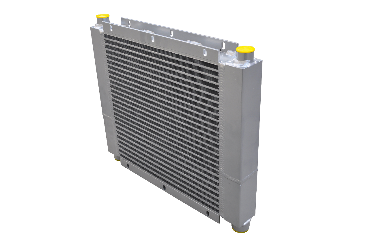
Product name : OEM Aluminum Plate Bar Fin Heat Exchanger
| NO. | ITEM | CONTENT DESCRIPTION | ||
| 1 | Material | Aluminum alloy, AA3003 is commonly used | ||
| 2 | Outer Dimension Limit | Outer Dimension Limit | ||
| 3 | Production Technique | Vacuum brazing and arc welding | ||
| 4 | Outer Dimension Limit | Max. 4000*4000*1000mm L*W*H | ||
| 5 | Working Pressure | Max 2Mpa | ||
| 6 | Thermal capacity | 50 Kw | ||
| 7 | Gas flow rate | 1 kg/s | ||
| 8 | Inlet temperature | 100 ℃ | ||
| 9 | Outlet temperature | 50 ℃ | ||
| 10 | Cold air inlet / outlet temperature | 50 ℃ / 61 ℃ | ||
| 11 | Cold air flow rate | 4.5 kg/s | ||
A plate fin heat exchanger is a type of heat exchanger that uses a series of flat, rectangular plates with fins attached to them. The fins increase the surface area of the plates, allowing for better heat transfer between the two fluids.
The structure of a plate fin heat exchanger consists of several layers of plates stacked together, with alternating hot and cold fluid flow channels. The plates are typically made of aluminum or stainless steel, which have high thermal conductivity to facilitate efficient heat transfer. The fins are attached to the plates and are usually arranged in a staggered pattern to maximize the surface area.


M-stirling’s plate fin heat exchanger technologies include
◆ Vacuum brazed and arc welding
◆ Controlled atmosphere brazed and arc welded
◆ Aluminum die casting for tanks manufacturing
◆ Aluminum extrusion for side bars manufacturing
◆ Sheet metal fabrication for shroud and other parts manufacturing

OEM Aluminum Plate Bar Fin Heat Exchanger Core

Related Heat Exchanger Products

About plate fin heat exchanger
A plate-fin heat exchanger is a type of heat exchanger design that uses plates and finned chambers to transfer heat between fluids, most commonly gases. It is often categorized as a compact heat exchanger to emphasize its relatively high heat transfer surface area to volume ratio. The plate-fin heat exchanger is widely used in many industries, including the aerospace industry for its compact size and lightweight properties, as well as in cryogenics where its ability to facilitate heat transfer with small temperature differences is utilized.

The working principle of a plate fin heat exchanger involves the transfer of heat between two fluids that flow in separate channels. One fluid, usually a hot fluid, flows through the hot fluid channels, while the other fluid, typically a cold fluid, flows through the cold fluid channels. The hot and cold fluids flow in opposite directions to optimize heat transfer.
As the hot fluid flows through the hot fluid channels, heat is transferred from the fluid to the plates and fins. The fins increase the surface area, allowing for more efficient heat transfer. The heat is then conducted through the plates to the cold fluid channels, where it is transferred to the cold fluid.
The efficiency of a plate fin heat exchanger depends on factors such as the thermal conductivity of the plates and fins, the flow rates of the hot and cold fluids, and the temperature difference between the fluids. By maximizing the surface area and promoting turbulent flow, plate fin heat exchangers can achieve high rates of heat transfer.
Applications
Plate fin heat exchangers are commonly used in various applications, such as air conditioning systems, refrigeration systems, and industrial processes, where efficient heat transfer is required. They offer advantages such as compact size, lightweight construction, and high heat transfer rates.

M-stirlings's plate fin heat exchangers are widely used in below fields
● Construction Equipment
● Agricultural and forestry machinery
● Green Energy
● Railway vehicles
● Compressor Dryers
● Hydraulic Systems
● Auto Industry
● Air Separation Chemical Industry
Product name : OEM Aluminum Plate Bar Fin Heat Exchanger
| NO. | ITEM | CONTENT DESCRIPTION | ||
| 1 | Material | Aluminum alloy, AA3003 is commonly used | ||
| 2 | Outer Dimension Limit | Outer Dimension Limit | ||
| 3 | Production Technique | Vacuum brazing and arc welding | ||
| 4 | Outer Dimension Limit | Max. 4000*4000*1000mm L*W*H | ||
| 5 | Working Pressure | Max 2Mpa | ||
| 6 | Thermal capacity | 50 Kw | ||
| 7 | Gas flow rate | 1 kg/s | ||
| 8 | Inlet temperature | 100 ℃ | ||
| 9 | Outlet temperature | 50 ℃ | ||
| 10 | Cold air inlet / outlet temperature | 50 ℃ / 61 ℃ | ||
| 11 | Cold air flow rate | 4.5 kg/s | ||
A plate fin heat exchanger is a type of heat exchanger that uses a series of flat, rectangular plates with fins attached to them. The fins increase the surface area of the plates, allowing for better heat transfer between the two fluids.
The structure of a plate fin heat exchanger consists of several layers of plates stacked together, with alternating hot and cold fluid flow channels. The plates are typically made of aluminum or stainless steel, which have high thermal conductivity to facilitate efficient heat transfer. The fins are attached to the plates and are usually arranged in a staggered pattern to maximize the surface area.


M-stirling’s plate fin heat exchanger technologies include
◆ Vacuum brazed and arc welding
◆ Controlled atmosphere brazed and arc welded
◆ Aluminum die casting for tanks manufacturing
◆ Aluminum extrusion for side bars manufacturing
◆ Sheet metal fabrication for shroud and other parts manufacturing

OEM Aluminum Plate Bar Fin Heat Exchanger Core

Related Heat Exchanger Products

About plate fin heat exchanger
A plate-fin heat exchanger is a type of heat exchanger design that uses plates and finned chambers to transfer heat between fluids, most commonly gases. It is often categorized as a compact heat exchanger to emphasize its relatively high heat transfer surface area to volume ratio. The plate-fin heat exchanger is widely used in many industries, including the aerospace industry for its compact size and lightweight properties, as well as in cryogenics where its ability to facilitate heat transfer with small temperature differences is utilized.

The working principle of a plate fin heat exchanger involves the transfer of heat between two fluids that flow in separate channels. One fluid, usually a hot fluid, flows through the hot fluid channels, while the other fluid, typically a cold fluid, flows through the cold fluid channels. The hot and cold fluids flow in opposite directions to optimize heat transfer.
As the hot fluid flows through the hot fluid channels, heat is transferred from the fluid to the plates and fins. The fins increase the surface area, allowing for more efficient heat transfer. The heat is then conducted through the plates to the cold fluid channels, where it is transferred to the cold fluid.
The efficiency of a plate fin heat exchanger depends on factors such as the thermal conductivity of the plates and fins, the flow rates of the hot and cold fluids, and the temperature difference between the fluids. By maximizing the surface area and promoting turbulent flow, plate fin heat exchangers can achieve high rates of heat transfer.
Applications
Plate fin heat exchangers are commonly used in various applications, such as air conditioning systems, refrigeration systems, and industrial processes, where efficient heat transfer is required. They offer advantages such as compact size, lightweight construction, and high heat transfer rates.

M-stirlings's plate fin heat exchangers are widely used in below fields
● Construction Equipment
● Agricultural and forestry machinery
● Green Energy
● Railway vehicles
● Compressor Dryers
● Hydraulic Systems
● Auto Industry
● Air Separation Chemical Industry

